My Chamberlain RJO101 installation: wiring, myQ setup, and troubleshooting
My Chamberlain RJO101 installation notes cover reusing suitable low-voltage wire, fixing a splice, clearing a 1-up/1-down code, myQ, and the LED light.
The cleanest part of my RJO101 installation came from reusing a suitable, disconnected low-voltage cable route. Verifying each conductor and testing the splice before closing it saved a visible ceiling run and made the final installation much neater.
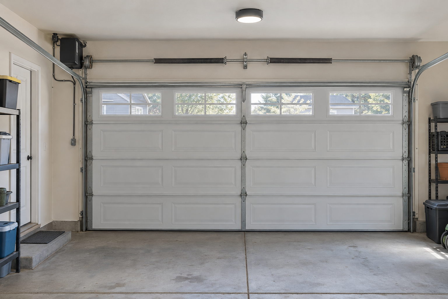
I replaced a ceiling-mounted LiftMaster opener with a Chamberlain RJO101. The mechanical installation was only part of the job. The details that took the most thought were the wall-control wiring, reused sensor cable, a failed splice, myQ setup, and the remote LED light. These are the notes I wish I had before I started. Use them alongside the current RJO101 owner’s manual for your exact door and hardware.
Why I switched to a wall-mount opener
The RJO101 mounts beside the garage door and turns the torsion shaft, so it does not need a motor and trolley rail across the ceiling. For me, that meant more usable overhead space and a much cleaner-looking garage.
Chamberlain lists built-in 2.4 GHz Wi-Fi with myQ control, battery backup, a remote LED garage light, and an automatic door lock among the RJO101’s features. Those were useful bonuses, but reclaiming the ceiling was the main reason I made the change.
The installation order that helped
I did not dismantle the old ceiling unit at the beginning. I left it mounted while I staged the RJO101, which gave me time to understand the new wiring before removing the rail and ceiling hardware.
I did not operate the RJO101 against an attached trolley or door arm. Before operating the new opener, the old system must be unplugged and mechanically disconnected so it cannot resist the door. Follow the RJO101 manual’s sequence for your door, including its required door profile setup.
Safety sensors and the 1-up/1-down code
What I checked during installation
The RJO101 uses a sending safety sensor with an amber LED and a receiving sensor with a green LED. Chamberlain says the sensors belong on opposite sides of the opening, no more than 6 inches above the floor. With a clear beam and correct alignment, both LEDs should glow steadily.
I connected the two-conductor sensor wiring to the opener terminals marked for the safety sensors. The current RJO101 instructions show both solid-white sensor leads in the WHITE terminal and both white-and-black leads in the GRAY terminal. Check the current manual and the labels on your own opener before terminating any conductor.
I avoided ordinary metal staples directly over the thin wire. A crushed or pierced conductor can create an intermittent fault. Insulated low-voltage staples, correctly sized clips, or small surface raceway are safer ways to keep the run tidy.
During my installation, the adjustment arrows alternated one UP flash and one DOWN flash. The current RJO101 manual identifies code 1-1 as safety sensors that are not installed or connected, or a cut sensor wire. I checked the LEDs, opener terminals, splices, and the full wire path. Once my sensor circuit was restored and both LEDs were steady, the opener operated normally. The manual assigns reversed or shorted wiring and misalignment to different codes, so read the complete blink pattern before changing anything.
The best wiring trick from my installation
My old ceiling opener already had concealed low-voltage cables for the wall controller and both safety sensors. Instead of running a visible new wall-control cable across the ceiling, I repurposed one disconnected old sensor cable as part of the wall-control path.
Inspect the existing low-voltage routes before pulling new cable. A suitable unused cable may give you a cleaner path, but verify its gauge, insulation, condition, routing, and compatibility first. Do not combine circuits or reuse a cable that is still connected to a sensor or other equipment.
My reused cable had red, white, and blue conductors. I used red and white for the two wall-control conductors and isolated the unused blue conductor at both ends. This describes my installation; it is not a universal color code.
RJO101 wall-control terminals
            │
            ▼
reused, disconnected sensor cable
            │  existing concealed route
            ▼
old ceiling-opener location
            │  accessible splice
            ▼
existing wall-control cable
            │
            ▼
new RJO101 wall control
Chamberlain sells a compatible two-conductor bell-wire kit for RJO101 wall controls and terminals. That supports the general use of low-voltage bell wire, but it does not automatically approve every existing cable or splice. If you are unsure about the wire type or local requirements, replace the run or ask a qualified installer.
How I identified and spliced the old wiring
Using continuity mode
With power disconnected and each cable removed from every device, I used a multimeter’s continuity mode to identify the runs. I temporarily joined two conductors at one end, tested the candidate pair at the other end, and then separated them to confirm the reading disappeared. I never used continuity mode on an energized circuit.
I labeled each cable as soon as I identified it: old left sensor, old right sensor, wall control, and RJO101 wall control. I also kept the chosen conductors consistent from one end of the route to the other.
The gel-connector problem
My stripped test connection worked. After I installed a gel-filled low-voltage connector, the wall control stopped working. The gel was not the likely electrical cause; the small conductors had shifted enough to leave a poor mechanical connection. Redoing the splice fixed it.
The lesson was to use a listed connector rated for the actual conductor size, tug-test each conductor, and test the circuit again before closing the splice. I avoided oversized connectors intended for typical household branch-circuit wire.
Finishing the ceiling splice
I placed the completed low-voltage splice in a small accessible white surface box with a blank cover, labeled it “RJO101 WALL CONTROL — DO NOT DISCONNECT,” and left a modest service loop. I ran the remaining cable in straight lines with small clips rather than diagonal runs across the wall.
Removing the old ceiling opener
Once the new opener, controls, lock, and safety systems worked correctly, I removed the old ceiling unit with the door fully closed. I unplugged it, disconnected its low-voltage wiring and door arm, supported the motor and rail before removing their fasteners, and then removed the unnecessary hanging brackets.
Removing an opener is separate from servicing the counterbalance system. I left the torsion springs, shaft, drums, lift cables, and spring anchors alone.
Connecting myQ and pairing the Smart LED light
I finished the physical installation and confirmed that the door worked correctly from its controls before starting Wi-Fi setup. Then I opened the myQ app, chose the option to add a garage-door opener, selected the wall-mount type, and followed the current prompts to connect the RJO101 to my 2.4 GHz network. App labels can change, so the current in-app directions and RJO101 manual take priority over these notes.
The RJO101 has its myQ gateway built in, so it does not need a separate hub. The current setup guide also says to synchronize the supplied wall control and run one complete door cycle before Wi-Fi programming.
When the remote Smart LED garage light did not respond as expected, I paired it again. The included MYQLED2 is normally factory paired. For an additional or replacement light, its current instructions say to press the light’s Learn button until its green LED comes on and then press the opener’s Learn button; one blink confirms pairing. I did this only after the opener and safety sensors were working.
Can you reuse an old LiftMaster wall control?
I reused a cable route, not an unverified old control. Chamberlain includes a motion-detecting wall control with the RJO101. Compatibility varies by control model and generation, so I would not assume an older LiftMaster wall station is compatible without checking its exact model against the current manual or asking Chamberlain.
My biggest RJO101 installation tips
| What helped | Why it mattered |
|---|---|
| Stage the new opener before removing the old hardware | It gave me time to understand the new layout. |
| Disconnect the old trolley and door arm before testing | The two opener systems cannot resist each other. |
| Inspect suitable existing low-voltage wire routes | I avoided a new exposed ceiling run. |
| Identify cables with power off and label them | It removed guesswork at the old opener location. |
| Use connectors rated for the actual wire size | The first finished splice failed when a thin conductor shifted. |
| Enclose and label the accessible splice | The result looks finished and remains serviceable. |
| Set up myQ after basic operation works | I could troubleshoot one system at a time. |
| Pair the Smart LED light last | The opener was already confirmed before I added the accessory. |
The final result
The biggest payoff was the clean ceiling. The old motor, long rail, door arm, hanging brackets, and visible wiring were gone. Reusing one suitable low-voltage cable route for the wall control made the finished installation even cleaner.
Before calling the job complete, I tested normal operation, the safety sensors, the automatic lock, battery backup, wall and remote controls, myQ, and the LED light. Chamberlain also requires a safety-reversal test after adjustments and monthly afterward. The door must reverse when it contacts a 1½-inch-high object, such as a 2×4 laid flat; if it does not, stop using the opener and have the system corrected.
Official RJO101 references
- RJO101 product page, specifications, and owner’s manual
- Chamberlain garage-door-opener diagnostic codes
- Chamberlain safety-sensor identification and placement
- Chamberlain safety-sensor wiring instructions
- Chamberlain light-control pairing instructions
- Chamberlain wall-mount myQ setup guide
- Chamberlain safety-reversal test instructions
Safety disclaimer: This article documents my personal installation experience and low-voltage wiring lessons. Always follow the current Chamberlain RJO101 owner’s manual, the instructions supplied with your unit, and applicable electrical and building requirements. Use a qualified garage-door technician for spring, cable, drum, shaft, balance, or structural work.
Editorial note: Adapted from my installation notes. The featured image is illustrative. Private identifiers and details about my home have been omitted. Product instructions can change, so the current manufacturer manual takes priority.